


Direct Imaging Auxiliary Functions Instrument
Scientist
Dr. Phillip MacQueen
(512) 471-1470
Instrument paper (to be written)
User manual (to be written)
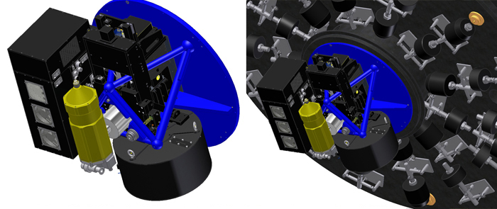
DIAFI is a computerized instrument used for CCD imaging through filters at the f/8.8 focus of the 107” HJST. It has a maximum field of view of 8.8 arcminutes square, and a 300–1050 nm bandwidth. The functions provided by DIAFI in support of CCD imaging are mounting the CCD detector system to the telescope, a 40-filter filter changer, an offset guider with filters and independent focus control, a zero power dissipation shutter, a deployable frame transfer mask, and a neutral density filter that can be used in series with the science filters.
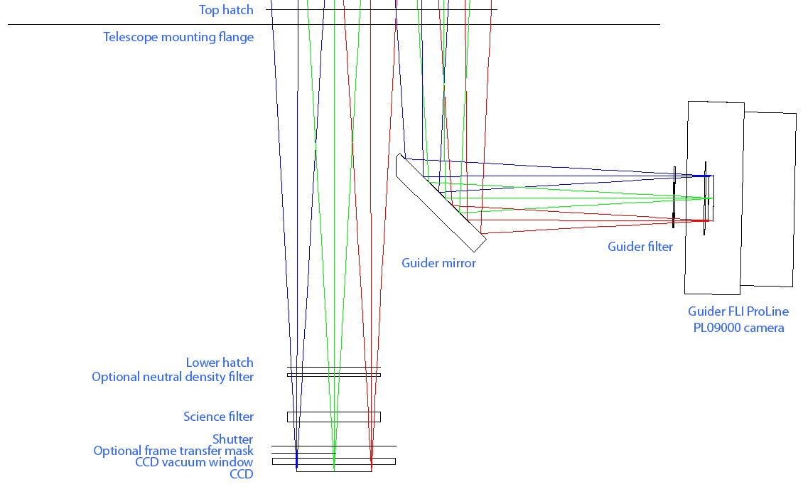
An optical diagram of the science and guider lights paths is at this DIAFI optics link.
DIAFI went into service in October 2011.
Detectors: DIAFI is used with a compatible detector system. Initially following commissioning, the detector system available for DIAFI will be TK3. A new CCD system called EV1 will become the primary detector when it is completed.
TK3 is a Tektronix 2048x2048, 24 micron pixel, backside illuminated, anti-reflection coated CCD. DIAFI with TK3 has a 7 arcminute square field of view. TK3 is typically binned 2x2, corresponding to 0.41 arcsecond square pixels. The readout rate is typically 100 kilopixels per second, with a readout noise of 4.2 electrons and a gain of 0.584 electrons per data unit. When narrow band filters are used and there is the possibility of being readout noise rather than sky noise limited, a readout rate of 50 kilopixels per second can be chosen, which has a readout noise of 3.0 electrons and a gain of 0.584 electrons per data unit. Full scale is 260,000 data units.
EV1 is an E2V 4096x4096, 15 micron pixel, backside illuminated, anti-reflection coated CCD. DIAFI with EV1 has an 8.8 arcminute square field of view. EV1 will typically be binned 3x3, corresponding to 0.39 arcsecond square pixels. The readout rate will be 100 kilopixels per second, with a readout noise of approximately 2 electrons, and a gain of 0.75 electrons per data unit. Full scale is 260,000 data units.
Filters: The DIAFI filter carousel can hold 40 filters. There are currently 19 facility filters, including a Sloan Digital Sky Survey set, a Bessel-prescription Johnson set, eight H-alpha filters with various FWHM values and red shifts, and one O[III] filter at z=0.05. Transmission curves and data files for all the filters - see below.
DIAFI facility filter set
Transmission as a function of wavelength data is available in both numerical and graphical from for each filter in the set of DIAFI facility filters. That data is in the Excel spreadsheet at the ![]() DIAFI filter spreadsheet link (version 2016-02-21).
DIAFI filter spreadsheet link (version 2016-02-21).
The DIAFI Broad band filters
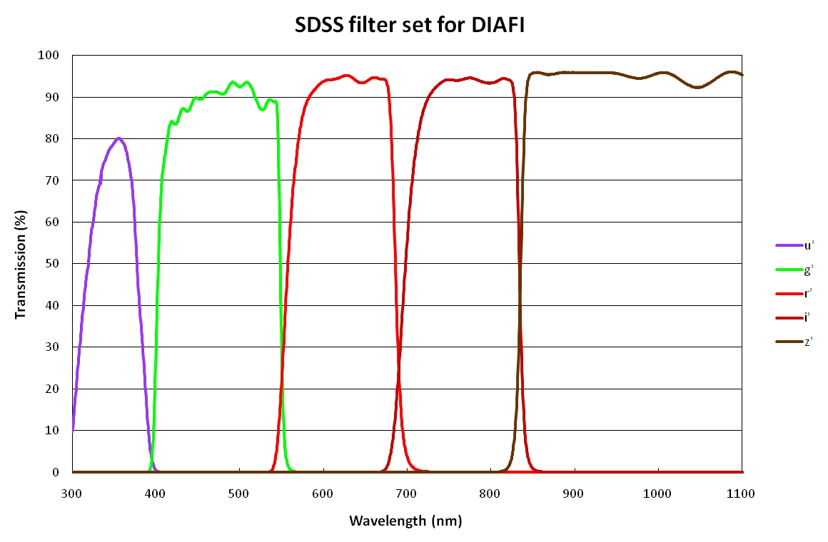
Sloan Digital Sky Survey filters: DIAFI has a full set of u’ g’ r’ i’ and z’ filters. Their transmission as a function of wavelength can be seen at this SDSS filters link.
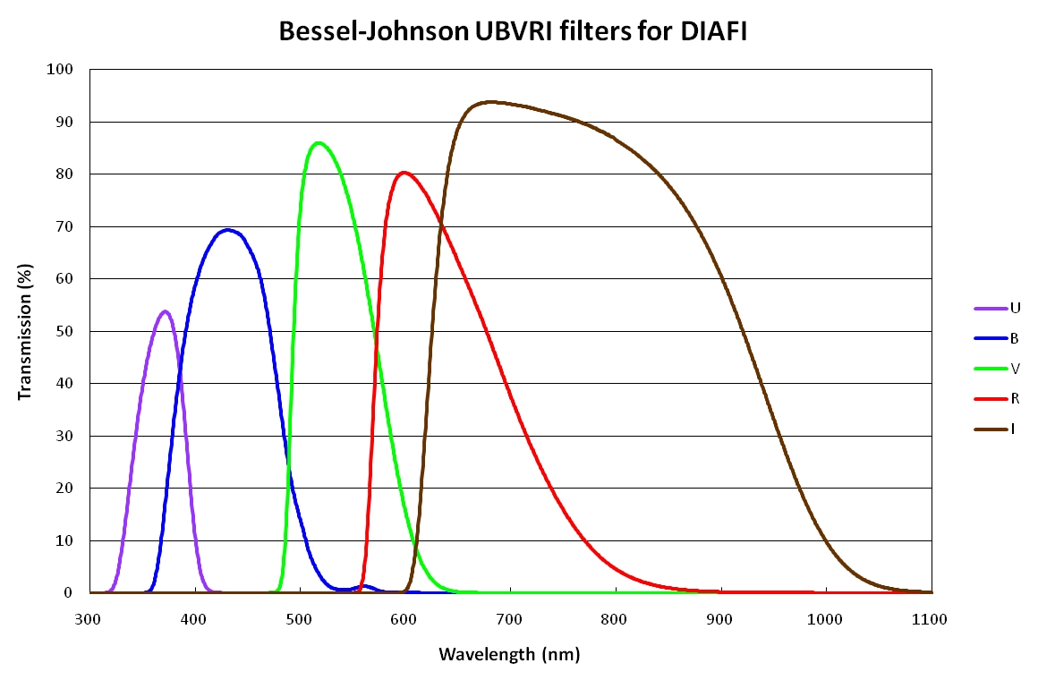
Bessel-prescription Johnson filters: DIAFI has a full set of U B V R and I filters. Their transmission as a function of wavelength can be seen at this UBVRI filters link.
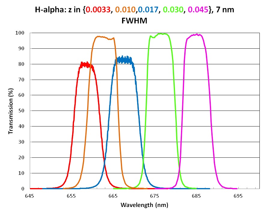
The DIAFI narrow band filters
| Spectral feature | z | FWHM (nm) |
Central λ (nm) |
Transmission plots | Filter name |
| H-alpha (line) | 0.0 | 4.0 | 656.3 | Hα-0-4nm | Halpha_656.3nm_4nm_z0 |
| H-alpha (off-line) | 0.0 | 4.0 | 665.3 | Halpha_665.3nm_4nm_z0 | |
| H-alpha (line) | 0.0033 | 7.0 | 658.5 | Hα-7mm-filters | Halpha_658.5_7nm_z0.0033 |
| H-alpha (line) | 0.017 | 7.0 | 667.5 | Halpha_667.5_7nm_z0.017 | |
| H-alpha (line) | 0.030 | 7.0 | 676.0 | Halpha_676.0_7nm_z0.030 | |
| H-alpha (line) | 0.045 | 7.0 | 685.8 | Halpha_685.8_7nm_z0.045 | |
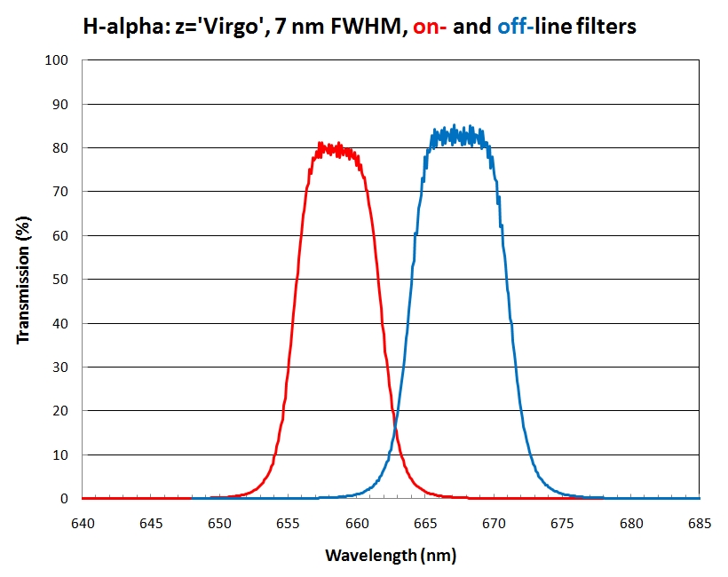
| H-alpha (line) | 0.0033 (Virgo) | 7.0 | 658.5 * | Hα-Virgo-7nm | Halpha_658.5_7nm_z0.0033 |
| H-alpha (off-line) | 0.0033 (Virgo) | 7.0 | 667.5 * | Halpha_667.5_7nm_z0.017 | |
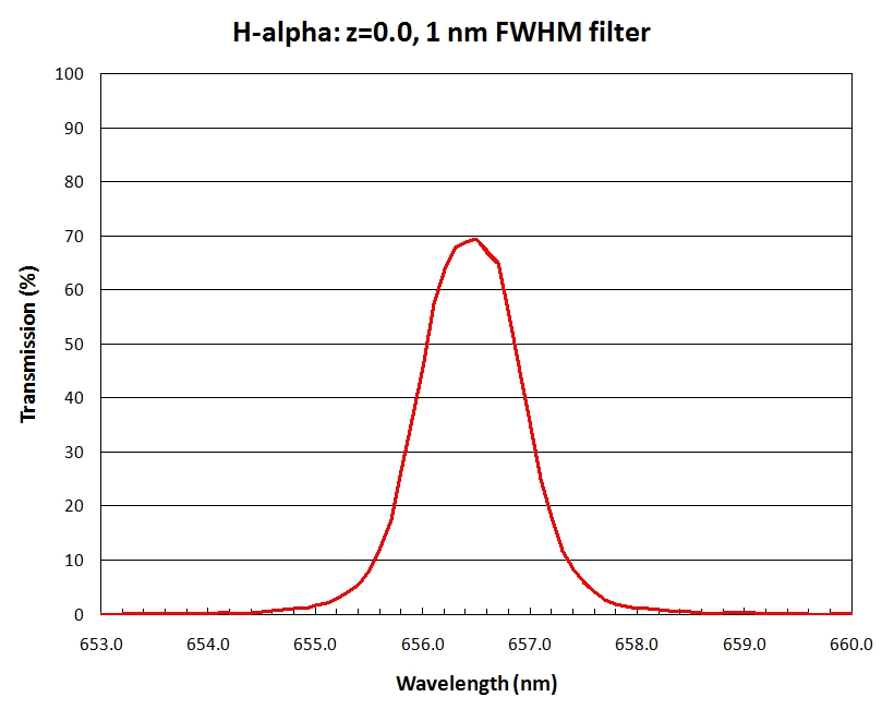
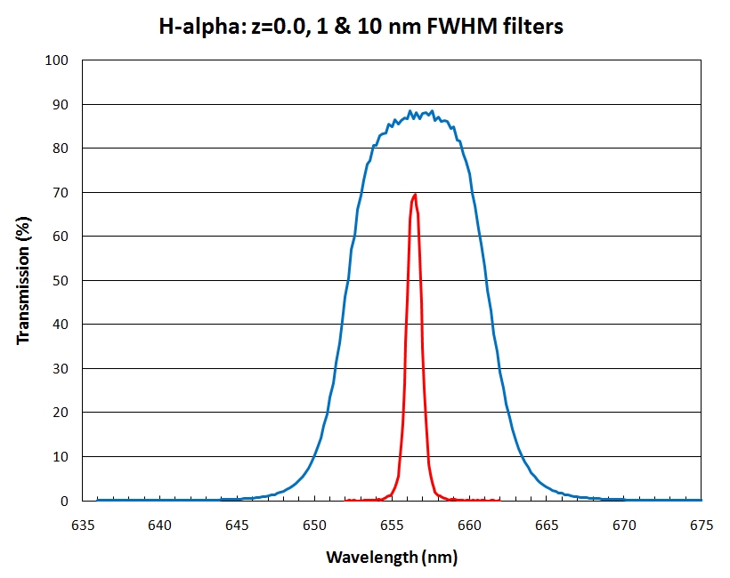
| H-alpha (line) | 0.0 | 1.0 | 656.28 | Hα-0-1nm | Halpha_656.3nm_1nm_z0 |
| H-alpha (line) | 0.0 | 10.0 | 656.3 | Hα-0-1&10nm | Halpha_656.3nm_10nm_z0 |
| O[III] (line) | 0.05 | 5.5 | 523.2 | O[III]-0.05-5.5nm | OIII_523.2nm_5.5nm_z0.05 |
* These 'Virgo' filters are two of the 7nm FWHM filter set
A neutral density filter can be deployed in series with a primary filter selected from the filter carousel. The ND filter attenuation is 5 stellar magnitudes (OD 2.0), and covers the full 300-1100 nm bandwidth of DIAFI. The filter has a metalized, reflective neutral density coating on one surface, and an 1.1% anti-reflection coating on its other surface. The AR coating reduces the filter ghost brightness so that the ghost is 5 magnitudes fainter than the primary image. The ghost is 5.7 arcseconds out of focus, and this defocus reduces the surface brightness of the ghost by about 3.5 magnitudes relative to an in-focus ghost in good seeing.
Standard DIAFI filters measure 3 x 3 inches and have a nominal thickness of 8 mm. If you wish to buy your own filters, please contact Phillip MacQueen for filter specifications and support in making the purchase. If a user needs to use smaller existing filters, and can accept the associated loss of field of view, please contact Phillip MacQueen and Anita Cochran at least 3 months ahead of the need. One exception is that filter frames will be available to mount two 2 x 2 inch filters.
Guiding: The guider camera is an FLI ProLine PL09000 with a 3056x3056 CCD. It views a 317 x 317 arcsecond field located 800 arcseconds from the center of the science field. The location of the guide field relative to the science field depends upon the mounting orientation of DIAFI on the telescope. In the default orientation, the guide field is to the south of the science field. The guide camera is normally binned 3x3 yielding 0.31 arcsecond square pixels. The readout and display time is 1 second. The guider does not look through the science filter, neutral density filter, frame transfer mask, or the science shutter.
The guider has high sensitivity due to both high quantum efficiency, and excellent broad band image quality. The guide camera is fed by a folding mirror from the telescope focal surface for broad band performance, and the folding mirror corrects the off-axis aberrations of the telescope to achieve seeing limited image quality.
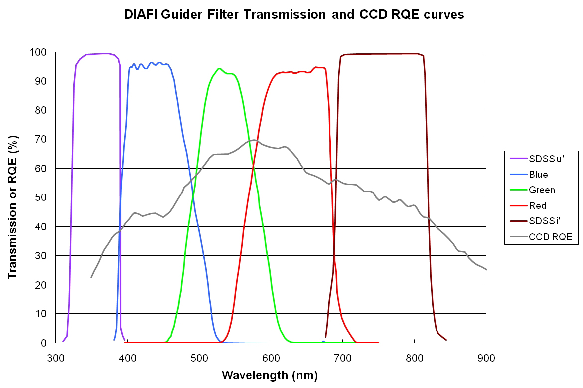
The guider has its own 5-filter filter wheel. The guider filters allow matching the guiding wavelength to the observation wavelength to minimize atmospheric chromatic refraction effects on image quality. The filter transmission curves and the guider CCD quantum efficiency curve are shown at this DIAFI guider link.
The telescope focus is used to focus the science CCD through the science filter. The guider has its own focus so that it can be parfocal with the science CCD regardless of the science filter or guider filter optical thickness. The guider focus is maintained automatically as filters are changed.
Interactive finder chart software is available at the telescope and elsewhere. It allows the science field of view to be positioned interactively on a digital sky survey image of the science field, and produces both a science field chart and an off-axis guider finder chart with the pixel coordinates of the suitable pointing/guide stars. This tool allows off-line planning for fast, precise acquisition of fields.
Shutter: the focal plane iris shutter has a minimum shutter time of 60 ms, and a minimum shutter cycle time of 125 ms. The shutter should not be cycled continuously at a rate faster than 2 Hz. The shutter operates with near-zero power dissipation as power is only dissipated during the 60 ms opening time, and the 65 ms closing time.
A FITS shutter correction frame is available along with an IRAF script for applying shutter corrections to short-integration-time data frames. This process corrects for the integration time being field-position dependent, increasing toward the field center, due to the opening and closing action of the iris shutter. Scripts are also available for taking the data necessary to make a shutter correction frame, and for building the shutter correction frame from that data set. Details and the files are available at this DIAFI shutter link.
Observing: DIAFI can be used efficiently by a single observer. DIAFI is run from the observing computer via a GUI and/or the ICE command line interface. Observing scripts can be used to control the telescope, instrument, and detector. The telescope can be taken over the axis with DIAFI. Observers new to observing with the HJST must receive training by either sitting in for 2 nights on an experienced observer’s observing run, or by having an experienced observer present for the first two nights of their own observing run.
Frame Transfer mode: To be written (ask pjm@wairau.as.utexas.edu)
Calibrations: the instrument is light tight allowing bias frames to be taken with the dome lights on. For flat fielding, the flat field screen in the crane wing of the dome can used in conjunction with quartz halogen lights mounted around the top edge of the telescope tube. Twilight flat field frames can also be taken at dusk and/or dawn. An observing script will be available to take the twilight flats through an observer specified filter set while maintaining a uniform exposure level across the set of frames as the twilight sky brightness changes.
DIAFI with VIRUS-P: DIAFI and VIRUS-P can be mounted on the 107” HJST together. An observer can swap between instruments in less than 10 minutes, so the potential exists to use both instruments in the same night. An observer interested in doing this should discuss it informally with Phillip MacQueen and Anita Cochran before proposing or requesting it (TAC or RFS).
Data reduction software: there is no DIAFI specific data reduction software with the exception of the shutter correction software described above in the shutter section. It is anticipated that the observer will use general software such as IRAF.
Acknowledgments: the DIAFI engineering team was Joe Strubhar, Gordon Wesley, Sam Odoms, Doug Edmonston, Jimmy Welborn, Rupert Ruiz, Bruce Cambell, Sherry Guthrie, and Phillip MacQueen. DIAFI and EV1 were built with McDonald Observatory funds, and the filter set was purchased with Department of Astronomy Cox funds. DIAFI was built in response to a request from the Forward Look Committee in 2007, based upon a proposal lead by Shardha Jogee.


![O[III]-0.05-5.5nm](/images/McDonaldObservatory/facilities-telescopes/diafi/OIII_z0p05_5p5nm_filter_curve.jpg)